Mixed-cell raceways offer best of two water worlds
Potential for retrofitting or for new production systems
Raceways have been used for years for the production of a wide range of aquaculture species and by governmental agencies for grow-out for stocking purposes. Raceways have many advantages, especially for grading and harvesting, and several major disadvantages in terms of discharge water quality and solids management. Currently, their use has been limited due to the unavailability of large quantities of high-quality source water, increased concerns about environmental impacts on receiving waters, and the difficulty in treating large effluent discharges.
One solution to these problems is to convert raceways into a series of counter-rotating mixed cells that act as hydraulically separated round tanks. This approach provides both the advantages of a raceway and the improved solids removal capability of circular tanks. The raceways could then be managed either as partial reuse systems or intensive recirculation systems.
Prototype raceway
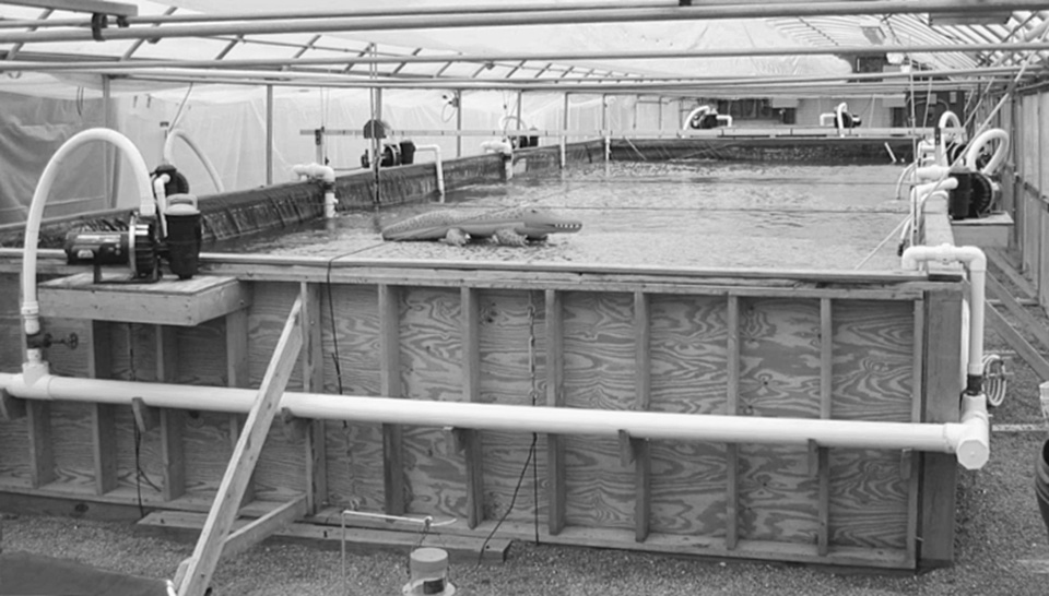
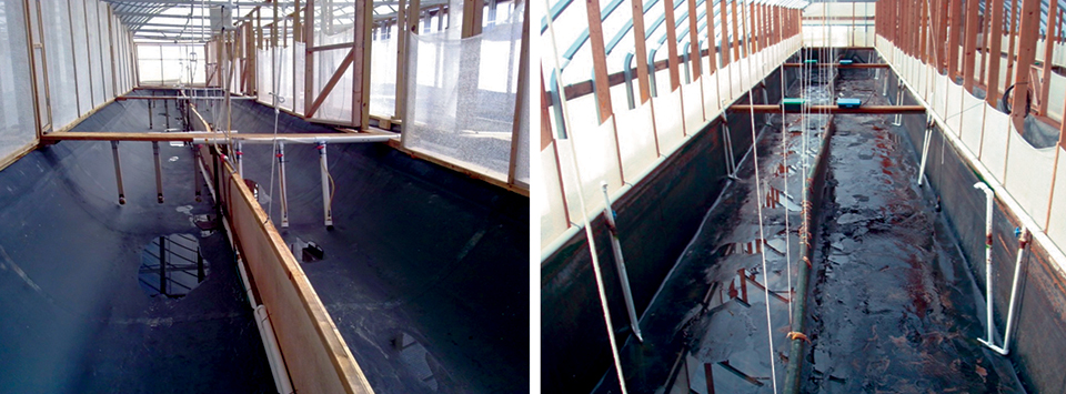
To better understand the operations, management, and hydraulics of a large, mixed-cell raceway, the authors constructed a prototype raceway using a research greenhouse at the Conservation Fund Freshwater Institute in Shepherdstown, West Virginia, USA. The work was supported by the U.S. Department of Agriculture’s Agricultural Research Service and Magnolia Shrimp, LLC, of Atlanta, Georgia.
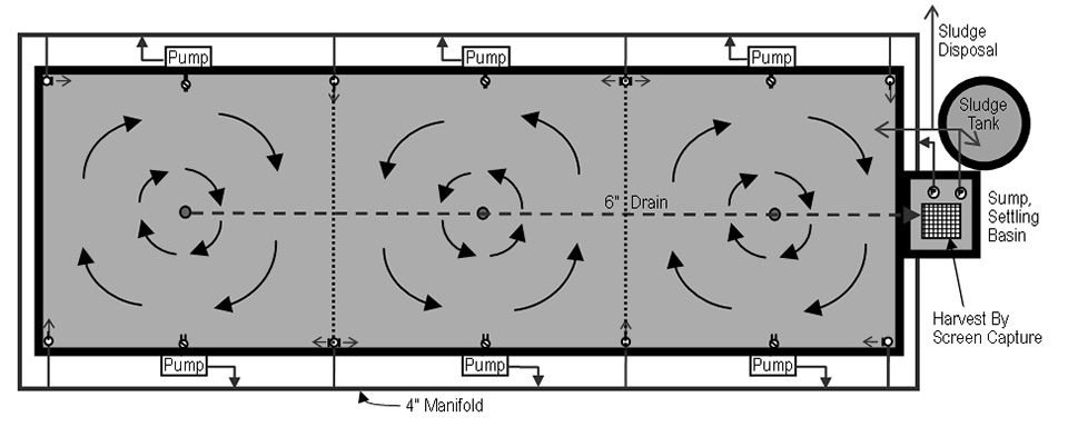
The basic design concept was to operate the raceway as a series of tanks or cells with individual center drains for continuous removal of solids and sludge.
Each cell received water from vertical PVC pipes in the corners of each cell through which water was tangentially pumped via jets to establish rotary circulation in the cells. The rotational velocity could be controlled by the design of the orifice discharges, either by increasing the flow rate, discharge velocity, or total number of jets. The orifice openings incorporated threaded bushings and plugs that allowed the effective orifice sizes to be easily modified.
Experience showed the tank rotational velocity was roughly proportional to the velocity through the orifices in the water inlet structure. This was then combined with the concept of the “Cornell double-drain system,” where 10 to 20 percent of the total flow was removed from a center bottom drain and 80-90 percent of the remainder was removed from the side drain. Settled wastes and sludge were removed from the center drains and collected in a settling sump.
Design and construction
The experimental raceway measured 16.3 meters x 5.44 meters x 1.22 meters and was constructed of structural lumber with a high-density, cross-laminated polyethylene liner. The walls and floor were insulated with 2.54-cm foam insulation board to minimize heat loss. The floor of the raceway was covered with 5 cm of fine sand and graded to provide a slight slope to the three center drains.
A 15.24-cm drain line with discharge drains centered on each of the three cells was buried along the longitudinal axis of the tank. The drains discharged into a 6.1-cubic-meter fiberglass sump tank with both a stand pipe and drain line to empty the system. The sump tank was intended to fulfill several roles, including solids management by acting as a settling basin, water level maintenance, and harvesting by draining the production tank through a screened cage.
Eight 0.75-kW pumps installed on platforms along the outside walls discharged into a 10-cm PVC manifold that encircled the raceway. Two pumps were located at the sump collection tank, while the remaining six were placed at equal distances along the length of the tank outside walls. The pump suction lines with check valves were located approximately one-third below the tank water level.
The pump discharges were connected to the manifold with a flexible hose and bronze gate valve to control flow. Placed along the side walls, eight down legs with multiple discharge orifices effectively divided the tank volume into three equal cells with counter-rotating water currents.
Flow measurement
An acoustic Doppler velocimeter designed for shallow water flow monitoring was used to measure speed and direction within the hydraulically separated cells. Water velocity was measured via the Doppler shift in frequency of sound from the small particulate matter in the water current.
An aluminum beam supported above the width of the raceway allowed the meter probe to be moved across the tank width. The probe was lowered into the tank to depths of 20, 50 and 95 cm below the water surface along a 0.5-meter grid system.
Hydraulic flows
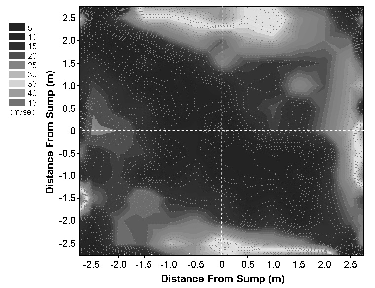
In Fig. 1, the color contour plot for the end cell farthest from the sump shows its velocity profile at intervals of 5 cm per second using down leg discharge orifices of 15 mm. Relatively high scouring velocities are seen at the outside perimeter of the cell, while velocity at the center near the drain is extremely low. The plot shows four discharge plumes and relatively uniform velocity in the midsection of the cell.
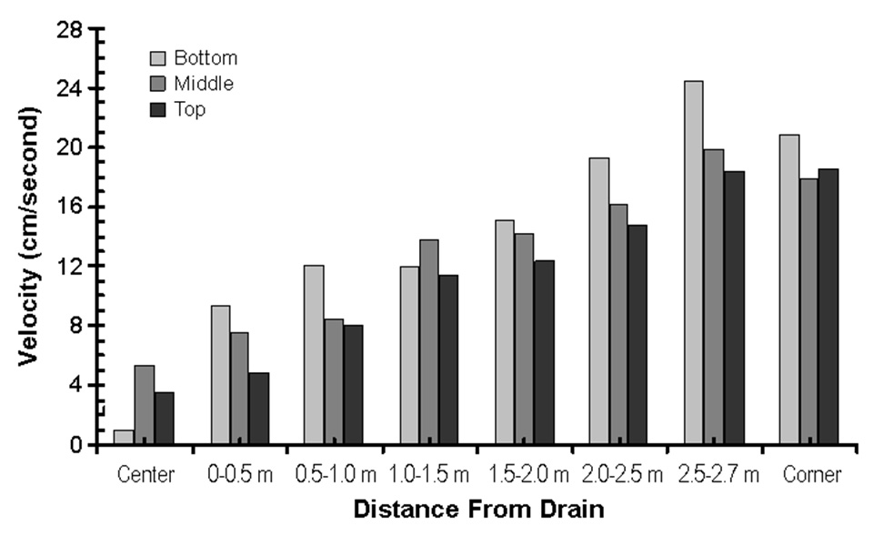
The velocity profile graph (Fig. 2) was created by averaging the velocities in an annular ring 0.5 meters thick starting at the center. The graph shows the almost linear velocity profile as a function of distance from the center drain. The bottom velocities were higher than the middle or top for this evalution because only the bottom five of seven orifices were open. This was done because the water depth was maintained lower than the design depth, and it was felt the top two orifices had only a minimum effect in creating the velocity profile.
Conclusion
Mixed-cell raceways show potential for either retrofitting existing raceways or as a design for a new production system. To better understand the hydraulics of a large, mixed-cell raceway, a prototype system was constructed at the Conservation Fund Freshwater Institute.
Preliminary results for studies of the velocity profiles within the cells showed excellent bottom velocities for scouring solids and moving them toward the center drain in each cell. Further work will focus on determining the relationships between the orifice velocities of water entering the cells and tank velocity, solids removal efficiency, and management studies on how best to use the sump tank for solids collection and settling.
(Editor’s Note: This article was originally published in the August 2004 print edition of the Global Aquaculture Advocate.)
Now that you've reached the end of the article ...
… please consider supporting GSA’s mission to advance responsible seafood practices through education, advocacy and third-party assurances. The Advocate aims to document the evolution of responsible seafood practices and share the expansive knowledge of our vast network of contributors.
By becoming a Global Seafood Alliance member, you’re ensuring that all of the pre-competitive work we do through member benefits, resources and events can continue. Individual membership costs just $50 a year.
Not a GSA member? Join us.
Authors
-

Environmental Engineer
Conservation Fund Freshwater Institute
1098 Turner Road
Shepherdstown, West Virginia 25443 USA -
Professor
Cornell University
Biological and Environmental Engineering Department
Ithaca, New York, USA
Related Posts
Responsibility
Advances in super-intensive, zero-exchange shrimp raceways
Research at the Texas AgriLife Research Mariculture Laboratory is investigating ways to improve the economic viability of super-intensive raceways for shrimp production.
Health & Welfare
A holistic management approach to EMS
Early Mortality Syndrome has devastated farmed shrimp in Asia and Latin America. With better understanding of the pathogen and the development and improvement of novel strategies, shrimp farmers are now able to better manage the disease.
Intelligence
A land grab for salmon (and shrimp) in upstate New York
The operators of Hudson Valley Fish Farm see their inland locale as a pilot to prove that land-based fish farming, located in close proximity to major metropolitan markets, can be successful.
Responsibility
A look at unit processes in RAS systems
The ability to maintain adequate oxygen levels can be a limiting factor in carrying capacities for RAS. The amount of oxygen required is largely dictated by the feed rate and length of time waste solids remain within the systems.